TM-9-2350-311-20-1 - Page 879 of 1275
TM9-2350-311-20-1
9-9 SHIFT CONTROL LINKAGE AND NEUTRAL SAFETY SWITCH ADJUSTMENT —
CONTINUED
b. Disassembly—Continued
5
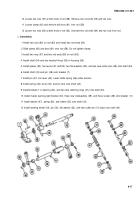
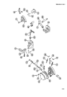
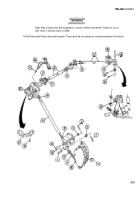
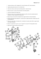
Remove lever (50) and shaft (51) from bracket (52). Remove grease fitting (53) from lever.
6 Remove pin (54), shaft (55), and bell crank (56) from support (57) to disassemble support assembly and base
assembly.
7 Remove two pins (58), two shafts (59), shaft (60), and link (61) from base (62).
8 Disconnect neutral safety switch (63).
9 Remove neutral safety switch and pin (63) from adapter (64).
10 Remove adapter (64) from base (62).
11 Remove cotter pin (65), straight pin (66), and lever (67) from base (62). Discard cotter pin.
12 Remove pin (68), spring (69), and contact pin (70) from lever (67).
c. Assembly
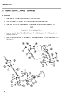
1 Install contact pin (70), spring (69), and pin (68) on lever (67).
2 Install lever (67), straight pin (66), and new cotter pin (65) on base (62).
3 Install adapter (64) in base (62).
4 Connect neutral safety switch (63).
5 Install link (61), shaft (60), two shafts (59), and two pins (58) on base (62).
6 Install bell crank (56), shaft (55), and pin (54) on support (57).
7 Install grease fitting (53) on lever (50). Install shaft (51) and lever on bracket (52).
8 Install lever (49), two pins (48), and two springs (47).
9 Install shift guide (46), cover (45), two new Iockwashers (44), two machine screws (43), three new Iockwashers
(42), and three screws (41). Install handle (40) and pin (39).
10 Install two nuts (36) and two rod ends (37) on rod (38). Tighten nuts.
9-24
Back to Top

