TM-9-2350-311-20-1 - Page 876 of 1275
6
7
8
9
10
11
TM9-2350-311-20-1
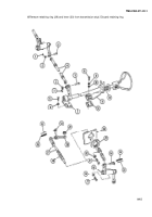
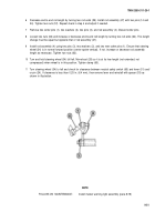
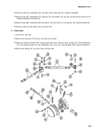
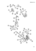
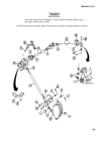
Decrease end-to-end rod length by turning two rod ends (59). Install rod assembly (27) with two pins (14 and
24). Tighten two nuts (57). Repeat check in step 4 and adjust if needed.
Remove two cotter pins (1), two washers (2), two pins (3), and rod assembly (4). Discard cotter pins.
Loosen two nuts (62) and increase or decrease end-to-end rod length by turning two rod ends (64). This length
change must be equal but opposite that of rod assembly (27).
Install rod assembly (4) using two pins (3), two washers (2), and two new cotter pins (1). Ensure that steering
wheel (34) is in normal forward position (center spoke vertical). If not, increase or decrease rod assembly
length as necessary. Tighten two nuts (62).
Turn and hold steering wheel (34) full left. Move boot (28) so it is at its free length (not extended, not
compressed) when wheel is in this position. Tighten clamp (60).
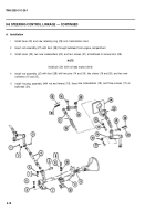
Turn steering wheel (34) to left and check for clearance between neutral safety switch (65) and lever (51) and/
or pin (24). If clearance is less than 0.25 in. (6.4 mm), then remove lever and reinstall with spacer (53) as
shown in illustration.
NOTE
FOLLOW-ON MAINTENANCE:
Install master warning light assembly (para 8-78)
9-21
Back to Top

