TM-9-2350-311-20-1 - Page 868 of 1275
TM9-2350-311-20-1
9-7 TRANSMISSION OIL SAMPLING COMPONENTS
This task covers:
a. Removal
b. Installation
INITIAL SETUP
T
OO
I
S
General mechanic’s tool kit (item 64, Appx H)
a. Removal
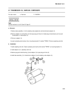
1 Remove tube assembly (1) from sampling valve adapter (2) and transmission adapter (3).
2 Remove adapter (3) and bushing (4) from pipe plug port hole (5). Install plug at transmission port to avoid
contamination of transmission oil.
3 Remove adapter (2).
4 Loosen sampling valve locknut (6) on mounting bracket (7) marked "TRANS”. Remove sampling valve (8).
b. Installation
1 Install sampling valve (8). Tighten sampling valve locknut (6) marked "TRANS” on mounting bracket (7).
2 install adapter (2) to sampling valve (8).
3 Remove plug and install bushing (4) and adapter (3) in pipe plug port hole (5).
4 Install tube assembly (1) to transmission adapter (3) and sampling valve adapter (2).
9-13
Back to Top

