TM-9-2350-311-20-1 - Page 864 of 1275
9-5 OIL FILTER
This task covers:
a. Removal
b. Disassembly
c. Assembly
d. Installation
I INITIAL SETUP I
Tools
Preformed packing (item 198, Appx G)
GeneraI mechanic’s tool kit (item 64, Appx H)
Self-locking nut (item 32, Appx G)
Materials/Parts
Filter element (item 218, Appx G)
Front slope plate removed (para 4-5)
Lockwashers (3) (item 89, Appx G)
a. Removal
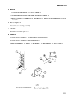
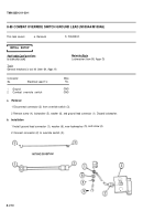
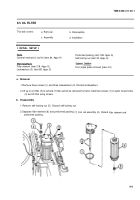
1 Remove three screws (1) and three Iockwashers (2). Discard Iockwashers.
2 Lift up on oil filter (3) to remove. If filter cannot be removed by hand, install two screws (1) in puller screw holes
(4) and lift filter using screws.
b. Disassembly
1 Remove self-locking nut (5). Discard self-locking nut.
2 Separate filter element (6) and preformed packing
preformed packing.
(7) from rod assembly (8). Discard filter element and
9-9
TM9-2350-311-20-1
Equipment Conditions
Back to Top

