TM-9-2350-311-20-1 - Page 872 of 1275
TM9-2350-311-20-1
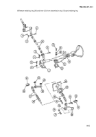
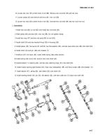
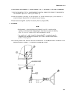
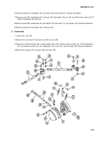
10 Loosen two nuts (57) at both ends of rod (58). Remove two rod ends (59) and two nuts.
11 Loosen clamp (60) and remove with boot (61) from rod (58).
12 Loosen two nuts (62) at both ends of rod (63). Unscrew two rod ends (64) and two nuts from rod.
c.
Assembly
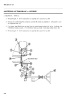
1 Install two nuts (62) on rod (63) and install two rod ends (64).
2 Slide clamp (60) and boot (61) onto rod (58). Do not tighten clamp.
3 Install two nuts (57) and two rod ends (59) on rod (58).
4 Install shaft (54) and two woodruff keys (55) in housing (56).
5 Install spacer (53), two levers (51 and 52), two flat washers (50), and two new cotter pins (49) onto shaft (54).
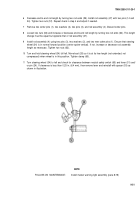
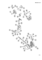
6 Install shaft (43) and pin (48) onto bracket (7).
7 Install pin (47) into lever (45). Lever holds spring (46) under tension.
8 Install spring (46), lever (45), and pin (44) onto shaft (43).
9 Install bracket (11), bearing (42), and two new retaining rings (41) onto shaft (43).
10 Install master warning light bracket (40), three new Iockwashers (39), and three screws (38) onto bracket (11).
11 Install washer (37), spring (36), and sleeve (35) over shaft (43).
12 Install steering wheel (34), pin (33), flat washer (32), and new cotter pin (31) back onto shaft (43).
9-17
Back to Top

