TM-9-2350-311-20-1 - Page 877 of 1275
TM9-2350-311-20-1
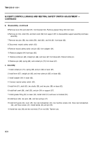
9-9 SHlFT CONTROL LINKAGE AND NEUTRAL SAFETY SWITCH ADJUSTMENT
This task covers:
a. Removal
b. Disassembly
c. Assembly
d. Installation
e. Adjustment
I INITIAL SETUP I
T
OO
I
S
Cotter pins (6) (item 39, Appx G)
General mechanic’s tool kit (item 64, Appx H)
Lockwashers (15) (item 95, Appx G)
Lockwashers (3) (item 96, Appx G)
Materials/Parts
Cotter pin (item 10, Appx G)
Cotter pin (item 29, Appx G)
Personnel Required
Two
a. Removal
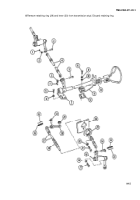
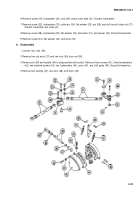
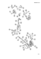
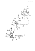
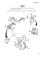
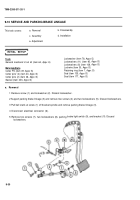
1 Remove two cotter pins (1), two flat washers (2), two pins (3), and shift control inner rod (4). Discard cotter
pins.
2 Remove three screws (5), three Iockwashers (6), and shift control (7). Discard Iockwashers.
3 Remove two cotter pins (8), flat washer (9), two pins (10), and shift control inner tube (11). Discard cotter pins.
4 Remove three screws (12), three Iockwashers (13), and support assembly (14). Discard Iockwashers.
5 Remove four screws (15), four Iockwashers (16), quick-release pin (17), and base assembly with shaft (18).
(Quick-release pin is located in powerplant compartment at bulkhead.) Discard Iockwashers.
9-22
Back to Top

