TM-9-2350-311-20-1 - Page 881 of 1275
TM9-2350-311-20-1
9-9 SHIFT CONTROL LINKAGE AND NEUTRAL SAFETY SWITCH ADJUSTMENT —
CONTINUED
d. Installation
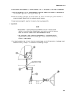
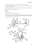
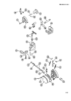
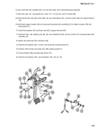
1 Install lever (35), flat washer (34), and screw (33).
2 Install spacer (32), bell crank (31), flat washer (30), new Iockwasher (29), and screw (28).
3 Install shift control outer rod (27), pin (26), flat washer (25), new cotter pin (24), new Iockwasher (23), and
screw (22).
4 Install shift control outer tube (21), new Iockwasher (20), and screw (19).
5 Install base assembly with shaft (18), quick-release pin (17), four new Iockwashers (16), and four screws (15).
(Quick-release pin is located in powerplant compartment at bulkhead.)
6 Install support assembly (14), three new Iockwashers (13), and three screws (12).
7 Install shift control inner tube (11), two pins (10), flat washer (9), and two new cotter pins (8).
8 Install shift control (7), three new Iockwashers (6), and three screws (5).
9 Install shift control inner rod (4), two pins (3), two flat washers (2), and two new cotter pins (1).
9-26
Back to Top

