TM-9-2350-311-20-1 - Page 889 of 1275
TM9-2350-311-20-1
9-10 SERVICE AND PARKING BRAKE LINKAGE — CONTINUED
b. Disassembly — Continued
18
19
20
21
22
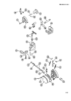
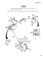
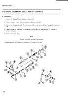
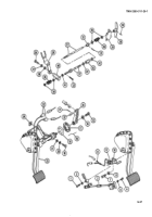
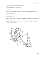
Loosen nut (76).
Remove cotter pin (77) and unscrew end (78) and clevis (79). Discard cotter pin.
Remove pin (80) and sprocket (81) (with chain) from clevis (79).
Remove two cotter pins (82), two clevis pins (83), and two clevises (84) (with chain) from right brake lever (85)
and left brake lever (86). Discard cotter pins.
Remove two pins (87) and separate sprocket control chain (88) from two clevises (84).
c. Assembly
1
2
3
4
5
Install separate chain (88) and two pins (87) into two clevises to assemble brake linkage.
Install two clevises (84) (with chain), two pins (83), and two new cotter pins (82) onto right brake Iever (85) and
left brake lever (86).
Install sprocket (81) (with chain) and pin (80) into clevis (79).
Install new cotter pin (77) and screw end (78) into clevis.
Tighten nut (76).
9-34
Back to Top

