TM-9-2350-311-20-1 - Page 891 of 1275
9-10 SERVICE AND PARKING BRAKE LINKAGE — CONTINUED
c. Assembly — Continued
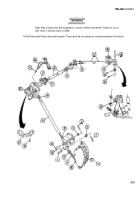
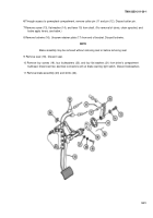
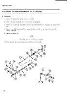
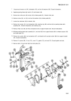
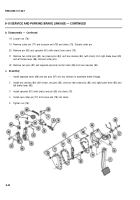
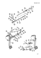
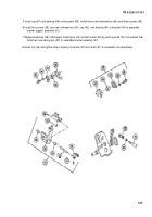
17 Install two nuts (42) on rods (27) and screw rods onto nut (43) to assemble brake linkage. Tighten nuts (42)
against nut (43).
18 Assemble bell crank (39), flat washer (38), new Iockwasher (37), and screw (36) to rod guide (40).
19 Install flat washer (41), rod guide (40), spring (35), two flat washers (34), and new cotter pin (33).
20 Install collar (32), pin (31), spring (30), two flat washers (29), and mounting bracket (28).
21 Install T-handle (26) and pin (25) at end of rod (27).
d. Installation
1
2
3
4
5
6
7
8
9
Install brake assembly (23) with four flat washers (21 ), four new Iockwashers (20), and four screws (19). Install
shims (24) as required.
Reconnect two electrical connectors (22) at brake warning light switch.
Install new seal (18).
Screw on retainer plate (17) on end of bracket. Install new Iockwire (16).
Install lever (15), flat washer (14), and screw (13) onto shaft. (For installation of clevis chain, sprocket, and
brake apply levers, see above.)
Install pin (12) and new cotter pin (11) through powerplant compartment access.
Install bracket (10) with two new Iockwashers (8) and two screws (7). Install parking brake light switch (9) and
reconnect electrical connector (6).
Place new Iockwasher (2) and bell crank of parking brake linkage (3) on screw (1) and screw onto bracket
spindle to install parking brake.
Install two new Iockwashers (5) and two screws (4), securing support of parking brake linkage (3).
9-36
TM9-2350-311-20-1
Back to Top


