TM-9-2350-311-20-1 - Page 912 of 1275
9-18 SPEEDOMETER AND TACHOMETER SYSTEMS
This task covers:
a. Removal
b. Installation
General mechanic’s tool kit (item 64, Appx H)
Gasket (item 56, Appx G)
Lockwashers (2) (item 95, Appx G)
Lockwashers (4) (item 192, Appx G)
Front slope plate removed (para 4-5)
Transmission access door opened (para 4-5)
a. Removal
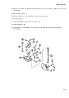
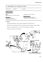
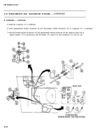
1 Remove flexible driveshafts (1 and 2) from back of speedometer (3) and tachometer (4).
2 Remove screw (5), Iockwasher (6), washer (7), and strap (8) in driver’s compartment. Discard Iockwasher.
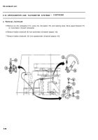
3 Remove four flexible driveshafts (1, 2,9, and 10) from two couplings (11) at bulkhead.
4 Remove two couplings (11) from bulkhead.
TM 9-2350-311-20-1
9-57
Back to Top

