TM-9-2350-311-20-1 - Page 919 of 1275
TM 9-2350-311-20-1
SECTION I. TRACKS
10-1 SUSPENSION IDENTIFICATION (ID)
Removal and installation procedures are shown for:
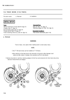
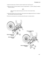
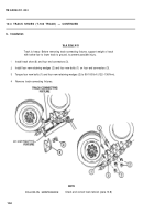
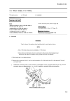
Track pads (para 10-2, T-136 track; para 10-4, T-154 track)
Track shoes (para 10-4, T-136 track; para 10-6, T-154 track)
Road wheels (para 10-10)
Road wheel arms (para 10-12)
Torsion bars (para 10-13)
Torsion bar anchors (para 10-14)
Track adjusters and mounting brackets (para 10-15)
Idler wheels and hubs (para 10-16)
Idler arm assemblies (para 10-17)
Idler arm housings (para 10-18)
Shock absorbers and mounts (para 10-19)
Shock absorber bearings (para 10-20)
Final drive sprockets and hubs (para 10-21)
Final drive assemblies (para 10-22)
Universal joints (para 10-23)
Disassembly and assembly procedures are given for road wheel hubs (para 10-11) and idler arm assemblies (para 10-
17).
This chapter also illustrates and
installation of thrown tracks (para
10-7, T-154 track).
describes disconnecting tracks (para 10-4, T-136 track; para 10-5, T-154 track),
10-6, T-136; para 10-7, T-154), and track replacement (para 10-6, T-136 track; para
Checking and adjusting of track tension are described in paragraph 10-8.
Notify support maintenance for disassembly and assembly of road wheel arm upper spindle and housing groups.
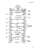
Vehicle suspension system is illustrated. Numbers 1 thru 7 refer to road wheel removal procedures in paragraph 10-10.
10-2
Back to Top

