TM-9-2350-311-20-1 - Page 965 of 1275
10-19 SHOCK ABSORBERS
This task covers:
a. Removal
b. Installation
Materials/Parts
General mechanic’s tool kit (item 64, Appx H)
Cotter pins (2) (item 48, Appx G)
Shock absorber puller (item 46, Appx H)
Seals (2) (item 156, Appx G)
Torque wrench (item 72, Appx H)
a. Removal
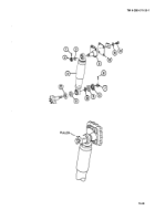
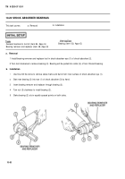
1 Remove cotter pin (1), nut (2), and flat washer (3). Discard cotter pin.
2 Screw shock absorber puller on threaded end of bearing. Turn screw head with wrench to pull shock absorber
from arm spindle on mount.
3 Remove top end of shock absorber (4) from shock absorber mount (5). Use puller if required.
4 Remove cotter pin (6), nut (7), retainer (8), seal (9), and flat washer (10). Discard cotter pin and seal.
5 Remove bottom end of shock absorber (4). Use puller if required.
6 Remove seal (11) and retainer (12). Discard seal.
7 Remove four screws (13) and four flat washers (14) from shock absorber mount (5). Remove mount and plate
(15) (front shock absorbers only).
b. Installation
1 Install shock absorber mount (5) and plate (15) (front shock absorbers only), four flat washers (14), and four
screws (13). Torque screws to 80-100 Ib-ft (108-136 N•m).
2 Install retainer (12) and new seal (11).
3 Install bottom end of shock absorber (4).
4 Install flat washer (10), new seal (9), retainer (8), nut (7), and new cotter pin (6). Torque nuts to 100-140 Ib-ft
(136-190 N•m).
5 Install top end of shock absorber (4) on mount (5).
6 install flat washer (3), nut (2), and new cotter pin (1). Torque nut to 100-140 Ib-ft (136-190 NŽm).
10-48
TM 9-2350-311-20-1
Back to Top

