TM-9-2350-311-20-1 - Page 972 of 1275
TM 9-2350-311-20-1
b.
Inspection
Compressed air for cleaning purposes will not exceed 30 psi (207 kPa). Use only with
effective chip guarding and personnel protective equipment (goggles/shield, gloves
etc.).
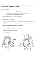
1 Inspect vent tube (5) and receptacle (19) for clogging. Clean tube with low-pressure compressed air, Clean
receptacle with soft brush or rag.
2 Remove 12 screws (20), 12 Iockwashers (21), end cover (22), and gasket (23). Discard Iockwashers.
3 Inspect retaining nut (24). If there are any visual signs of loose nut or sheared cotter pin (25), remove and
replace final drive assembly (7). Notify support maintenance.
4 Inspect gasket (23). Replace if worn or deteriorated.
5 Install gasket (23), end cover (22), 12 new Iockwashers (21 ), and 12 screws (20).
c.
Installation
1
2
3
4
5
6
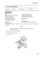
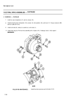
Install guide pins.
Coat contact surfaces of hull and final drive assembly (7) with zinc chromate primer before installation.
Install lifting eye bolt and lifting sling on final drive assembly (7). Slide final drive assembly over guide pins.
Install new top Iockwasher (13) and screw (12) and new bottom Iockwasher (1 5), screw (14), flat washer (1 6),
and nut (17) near bottom of final drive.
Remove guide pins, lifting eye bolt, and lifting sling. Install cap screw (18).
Install two new Iockwashers (9) and two screws (8).
10-55
WARNING
Back to Top

