TM-9-2350-311-20-1 - Page 958 of 1275
TM 9-2350-311-20-1
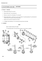
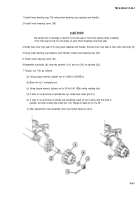
1 Install inner bearing cup (18) using inner bearing cup replacer and handle.
2 Install inner bearing cone (19).
CAUTION
Be careful not to damage or deform inner hub seal or inner hub seal lip when installing
inner hub seal in hub. Do not press on pins when installing inner hub seal.
3 Install new inner hub seal (16) using seal replacer and handle. Ensure inner hub seal is flush with hub body (8).
4 Using outer bearing cup replacer and handle, install outer bearing cup (20).
5 Install outer bearing cone (21).
6 Assemble hub body (8), new key washer (1 4), and nut (13) on spindle (22).
7 Torque nut (13) as follows:
(a) Using torque wrench, tighten nut to 100Ib-ft (136 NŽm).
(b) Back off nut 1 complete turn.
(c) Using torque wrench, tighten nut to 30 Ib-ft (41 NŽm) while rotating hub.
(d) If slots in nut and hole in spindle line up, install new cotter pin (12).
(e) If slots in nut and hole in spindle are misalined, back off nut to aline with first hole in
spindle, and then install new cotter pin (12). Range of back-off is 0 to 30°.
(f) After adjustment, hub assembly (23) must rotate freely by hand.
10-41
Back to Top

