TM-9-2350-311-20-1 - Page 949 of 1275
10-13 TORSION BARS — CONTINUED
b. Installation
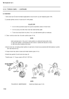
1 See torsion bar ID chart information applicable to torsion bar (4) you are replacing (para 10-9).
2 Lubricate splines at end of torsion bar (4) with grease.
3 Clean and
CAUTIO N
Do not remove protective tape from ground (unsplined) surface of torsion bars.
Do not use any tool other than torsion bar slide hammer puller.
Torsion bar should slide in by hand. If not, use slide hammer puller as necessary.
dry torsion bar (4) anchor cavities (para 10-14).
NOTE
Hold road wheel arms 1 thru 6 at 4 o’clock position on vehicle left side and 8 o’clock
on right; hold number 7 road wheel arm at 8 o’clock on vehicle left side and 4 o’clock
on right side while installing torsion bars.
4 Insert torsion bar (4) making certain splines on each end of torsion bar are alined with blind splines in anchor
and road wheel arm (5).
5 Torque torsion bar anchor screws and install Iockwire (para 10-14).
6 Install new gasket (3) and torsion bar plug (2).
7 Install screw (1). Torque screw to 90 Ib-ft (122 N·m).
NOTE
FOLLOW-ON MAINTENANCE:
Install road wheels (para 10-10)
10-32
TM 9-2350-311-20-1
Back to Top

