TM-9-2350-311-20-1 - Page 948 of 1275
TM 9-2350-311-20-1
FOLLOW-ON MAINTENANCE:
Install torsion bar (para 10-13)
Connect shock absorber for road wheel arms 1 and 7 (para 10-19)
Install road wheel (para 10-10)
10-13 TORSION BARS
This task covers:
a. Removal
b. Installation
T
OO
I
S
Gasket (item 196, Appx G)
General mechanic’s tool kit (item 64, Appx H)
Adapter (item 1, Appx H)
Personnel Required
Slide hammer puller (item 47, Appx H)
Two
Torque wrench (item 72, Appx H)
Torsion bar wrench (item 74, Appx H)
Equipment Conditions
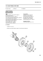
Road wheels removed (para 10-10)
Materials/Parts
GAA grease (item 25 or 26, Appx D)
a. Removal
NOTE
When removing torsion bar at number 1 (front) or number 7 (rear) road wheel position,
it will be necessary to disconnect shock absorber (para 10-19). Torsion bar anchor
screws must be loosened 1 full turn before attempting to remove or install torsion bars
(para 10-13).
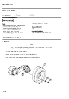
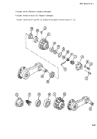
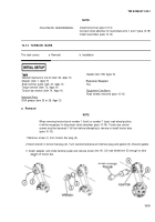
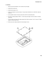
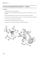
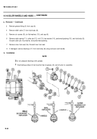
1 Remove screw (1) from torsion bar plug (2).
2 Insert wrench in torsion bar plug (2). Turn counterclockwise and remove plug and gasket (3). Discard gasket.
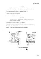
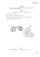
3 Install adapter and slide
weight off torsion bar.
hammer puller and remove torsion bar (4). Lift road wheel arm (5) enough to take
10-31
NOTE
Back to Top

