TM-9-2350-311-20-1 - Page 943 of 1275
TM 9-2350-311-20-1
10-11 ROAD WHEEL HUBS
This task covers:
a. Disassembly
b. Inspection and Repair
c. Assembly
General mechanic’s tool kit (item 64, Appx H)
Handle (item 28, Appx H)
Inner bearing cup remover/replacer (item 51, Appx H)
Inner seal replacer (item 50, Appx H)
Lubricating gun (item 24, Appx H)
Outer bearing cup remover/replacer (item 52, Appx H)
Torque wrench (item 72, Appx H)
Materials/Parts
Cotter pin (item 3, Appx G)
GAA grease (item 27, Appx D)
Inner hub seal (item 164, Appx G)
Key washer (item 185, Appx G)
Preformed packing (item 62, Appx G)
Personnel Required
i
Two
Equipment Conditions
Road wheels removed (para 10-10)
a. Disassembly
1
2
3
4
5
6
7
8
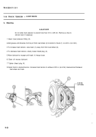
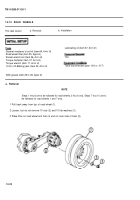
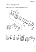
Remove grease fitting (1) from cap (2).
Remove relief valve (3) from hub assembly (4).
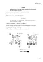
Remove six cap screws (5) and six washers (6). Remove cap (2).
Remove static spring (7), cotter pin (8), nut (9), key washer (10), and preformed packing (11). Discard cotter
pin, key washer, and preformed packing.
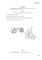
Using both hands, carefully slide road wheel hub (4) from road wheel arm spindle (12).
Remove inner hub seal (13). Discard inner hub seal.
Remove bearing cones (14 and 15) from hub (4).
If damaged, remove bearing cups (16 and 17) from hub (4), using remover and handle.
b. Inspection and Repair
1 Inspect cap (2). Replace if cracked, damaged, or defective.
2 Inspect static spring (7). Replace if defective.
3 Inspect outer bearing cone (17) (TM 9-214).
4 Inspect inner bearing cone (16) (TM 9-214).
10-26
Back to Top


