TM-9-2350-311-20-2 - Page 56 of 828
TM 9–2350–311–20–2
1–25
b.
Breech Assembly
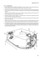
1
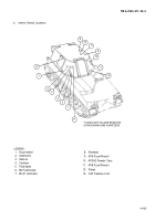
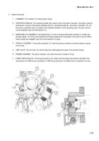
CHAMBER. The chamber (7) holds powder charge.
2
OPERATING HANDLE. The operating handle (8) is used to open the breech manually. The breech opening
mechanism consists of the breech operating cam (9), operating handle (8), and carrier
assembly (10). As
the cannon assembly returns to battery, the combined operation of the operating crank, the cam, and the
carrier assembly open the breechblock (11).
3
BREECHBLOCK ASSEMBLY. The breechblock (11) locks into place behind the chamber (7) holding the
powder charge. On closing, the breechblock threads engage with the threads of the breech ring (2). When
these threads are engaged, they lock the breechblock in place.
4
SPINDLE ASSEMBLY. The spindle assembly (12) seals the powder chamber to prevent escape of gases
into the cab.
5
VENT HOLE. The vent hole (13) directs the primer blast against the base of the powder charge.
6
PRIMER CHAMBER. The primer chamber (14) holds the primer in place for firing.
7
FIRING GROUP BLOCK. The firing group block (15) slides over the primer and positions the M35 firing
mechanism (on M185 cannon assembly) or M49 firing mechanism (on M284 cannon assembly) for firing.
12
14
9
8
7
11
15
13
2
10
12
Back to Top

