TM-9-2350-311-20-2 - Page 57 of 828
TM 9–2350–311–20–2
1–26
1–18 EQUIPMENT OPERATION AND DESCRIPTION — CONTINUED
1–18.1 Mount and Howitzer Assembly — Continued
a.
Mount Assembly
1
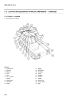
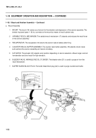
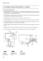
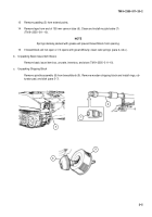
MOUNT. The mount (16) serves as a fulcrum for the elevation and depression of the cannon assembly. The
breech ring band (para 1–18.1a.) connects to the mount by means of recoil cylinder rods.
2
VARIABLE RECOIL MECHANISM. The variable recoil mechanism (17) absorbs and reduces the recoil force
of the cannon assembly.
3
RECUPERATOR. The recuperator (18) returns the cannon tube to battery after firing.
4
COUNTER RECOIL BUFFER ASSEMBLY. The counter recoil buffer assembly (19) absorbs shock; slows
and cushions the cannon assembly as it returns to battery.
5
ACTUATOR. The actuator (20) adjusts recoil position depending on cannon elevation. Allows longer recoil at
low elevation and short recoil for high elevation.
6
BLEEDER VALVE, VARIABLE RECOIL CYLINDER. The bleeder valve (21) is used to purge air from the
recoil mechanism.
7
BUFFER BLEED BLOCK PLUG. The buffer bleed block plug (22) is used to purge counterrecoil buffer.
16
17
21
18
22
20
19
17
Back to Top

