TM-9-2350-311-20-2 - Page 59 of 828
TM 9–2350–311–20–2
1–28
1–18 EQUIPMENT OPERATION AND DESCRIPTION — CONTINUED
1–18.3
Rammer Hydraulic System
a.
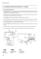
RAMMER ASSEMBLY. The rammer assembly (1) is used for loading and ramming the projectile into the cannon tube.
Hydraulic power from the power pack assembly (2) flows through the valve assembly to the rammer cylinder which
uses the pressure to ram the projectile into position.
b.
ACTUATING VALVE. The actuating valve (3) controls the inflow of hydraulic oil for the ramming operation and outflow
of hydraulic oil for the retraction of the rammer (1) after use.
c.
TRAY ASSEMBLY. The tray assembly (4) holds the projectile in position for ramming.
d.
CYLINDER ASSEMBLY. The cylinder assembly (5) contains the piston which rams the projectile into the chamber.
e.
MAIN RELEASE HANDLE. The main release handle (6) releases the locking mechanism so that the rammer (1) may
be moved into “RAM” position, and also back into “STOW” position.
f.
HANDLE ASSEMBLY. The handle assembly (7) provides a hand hold for rotating the rammer cylinder (5) into ramming
position.
g.
CYLINDER LATCH. The cylinder latch (8) locks the rammer cylinder (5) into position on the tray assembly (4).
h.
BLOCKING VALVE. The blocking valve (9) prevents accidental ramming of rammer in stowed position.
8
3
9
1
2
OPERATING
PRESSURE –
900 PSI (6206 kPa)
DRAIN RESERVOIR
PRESSURE – 0 PSI
(0 kPa)
PUMP PRESSURE –
925 – 1225 PSI
(6378 – 8446 kPa)
9
6
7
5
4
Back to Top

