TM-9-2350-311-20-2 - Page 58 of 828
TM 9–2350–311–20–2
1–27
1–18.2
Elevating System
a.
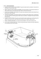
MAIN ACCUMULATOR AND POWER PACK ASSEMBLY. The main accumulator (1) and power pack assembly (2)
provide hydraulic power to cab components through a network of lines and control valves.
b.
SELECTOR VALVE ASSEMBLY AND SOLENOID. The selector valve assembly (3) and solenoid (4) direct hydraulic
flow from either the gunner’s control handle (5) or assistant gunner’s control handle (6) to the equilibrated elevating
cylinder (7).
c.
GUNNER’S CONTROL HANDLE. The gunner’s control handle (5) receives hydraulic power from power pack (2) to
elevate or depress the cannon and traverses cab left or right.
d.
ASSISTANT GUNNER’S CONTROL HANDLE. The assistant gunner’s control handle (6) receives hydraulic power
from the power pack (2) to elevate or depress cannon.
e.
MANUAL ELEVATING HAND PUMP. The manual elevation hand pump (8) directs hydraulic flow to elevate and de-
press the cannon manually.
f.
MANUAL ELEVATION ACCUMULATOR. The manual elevation accumulator (9) maintains hydraulic fluid in manual
elevation hand pump (8) under minimum pressure to permit manual control of cannon elevation and depression.
g.
EQUILIBRATED ELEVATING CYLINDER. The equilibrated elevating cylinder (7) elevates, depresses, and balances can-
non; as well as compensates for uneven distribution of weight of cannon tube. Other components of equilibration system
are the primary accumulator assembly (10), secondary accumulator assembly (11), equilibration manifold assembly (12),
and manual elevation hand pump (8).
1
2
7
9
3
8
6
4
11
12
10
5
Back to Top

