TM-9-2350-311-34-1 - Page 110 of 352
TM 9-2350-311-34-1
5-5 AIR CLEANER BLOWER MOTORS — CONTINUED
a. Disassembly — Continued
9
10
11
12
13
14
15
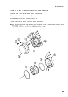
Remove self-locking nut (21). Unscrew impeller (22). Remove washers (23) (quantity will vary) and felt washer
(24). Discard self-locking nut.
NOTE
Follow step 10 for removal of both brush assembly holders.
Remove three screws (25), three Iockwasher’s (26), electrical lead (6), spring (27), and brushes (28) from
brush assembly holder (29). Discard Iockwashers.
Remove two screws (30) and two Iockwasher (31). Discard Iockwasher.
Separate motor cover (3), stator (32), armature (33), two bearings (34), and flat washer (35).
Remove screw (36) and clip (37) from commutator end bell (9).
Remove brush assembly holder (29) from commutator end bell (9).
Remove ground wire (38).
b. Inspection, Repair, and Test
1
2
3
4
5
6
7
8
9
Measure brushes (28). If less than 0.39 in. (9.9 cm), replace brushes.
Inspect brush assembly holder (29). Replace if brass fittings are cracked or damaged.
Inspect felt washer (24). Replace if cracked or distorted.
Inspect two bearings (34) (TM 9-214). Replace as required.
Test armature (33) on growler. Use lathe to turn down armature. Undercut mica 0.03 in. (0.8 mm) as required.
Test stator (32) for continuity. Replace if field winding is open or shorted.
Inspect motor cover (3). Replace if damaged or distorted.
Inspect washers (23). Replace if cracked or distorted.
Inspect impeller (22). Replace if nicked, cracked, or vanes are broken.
5-28
Back to Top


