TM-9-2350-311-34-1 - Page 122 of 352
INITIAL SETUP
Materials/Parts
Equipment Conditions
Tools
TM 9-2350-311-34-1
6-2 COOLING FAN DRIVE ASSEMBLY
This task covers:
a. Removal
b. Disassembly
c. Assembly
d. Installation
General mechanic’s tool kit (item 14, Appx C)
Dial indicator (item 4, Appx C)
Fabricated bracket (item 1, Appx D)
Micrometer (item 15, Appx C)
Support blocks (item 3, Appx C)
Toque wrench (item 28, Appx C)
Gaskets (2) (item 60, Appx F)
Gasket (item 62, Appx F)
Gasket (item 64, Appx F)
Key washer (item 6, Appx F)
Lockwashers (3) (item 30, Appx F)
Lockwashers (12) (item 37, Appx F)
Lockwire (item 9, Appx F)
Lubricant (item 10, Appx B)
Preformed packings (2) (item 14, Appx F)
Preformed packing (item 19, Appx F)
Preformed packing (item 20, Appx F)
Preformed packing (item 47, Appx F)
Preformed packings (2) (item 48, Appx F)
Retaining ring (item 5, Appx F)
Seal (item 65, Appx F)
Cooling fan universal joints removed (para 6-1)
a.
Removal
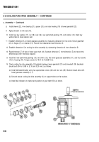
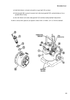
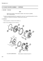
1 Remove 12 screws (1) and 12 Iockwasher (2). Discard Iockwasher.
2 Remove cooling fan drive assembly (3) and gasket (4). Discard gasket.
6-4
Back to Top


