TM-9-2350-311-34-1 - Page 128 of 352
TM 9-2350-311-34-1
6-2 COOLING FAN DRIVE ASSEMBLY — CONTINUED
c. Assembly - Continued
NOTE
Repeat same procedure for bevel gearcase assembly. Some cooling fan assemblies
may not include packings.
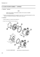
17 Install two new preformed packings (8), new gasket (6), input cover (7), new preformed packing (9), and two
screws (5) to cooling fan drive assembly (3). Apply lubricant to packing (9).
d. Installation
1 Install new gasket (4), cooling fan drive assembly (3).
2 lnstal l12 new Iockwasher (2) and 12 screws (1).
FOLLOW-ON
NOTE
MAINTENANCE:
Install cooling fan universal joints (para 6-1)
6-10
Back to Top


