TM-9-2350-311-34-1 - Page 126 of 352
6-8
TM9-2350-311-34-1
6-2 COOLING FAN DRIVE ASSEMBLY — CONTINUED
c. Assembly — Continued
8
9
10
11
12
13
14
15
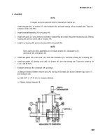
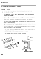
Install sleeve (22), inner bearing (21), spacer (20), and outer bearing (19) to bevel gearshaft (23).
Apply lubricant to new seal (16).
Install new key washer (17), nut (18), seal (16), new preformed packing (15), and retainer (14). Bend key
washer tabs to clear retainer wall.
Establish dimension A on bevel gearcase assembly by measuring distance from toe end of bevel gearshaft
(23) to flange (47) on retainer (14). Record this measurement as dimension A.
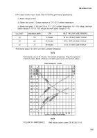
Establish dimension Con cooling fan drive assembly by subtracting dimension A from dimension B.
Read dimension Z off face of bevel gear shaft (23). Subtract dimension C from dimension Z and record this
difference as shim thickness required.
Install two new preformed packings (13), two shims (12), two bevel gearcase assemblies (11), and four screws
(10) to housing (44). Torque screws to 19-21 Ib-ft (2-28 N•m).
Check cooling fan drive assembly (3) backlash between bevel gearshaft (23) and driveshaft (39) (backlash
should be 0.004 to 0.008 in. [0.10 and 0.20 mm] ) as follows:
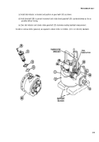
(a) Install fabricated bracket using two appropriate screws (48) and two nuts (49). Bracket should aline with
bevel gearcase assembly (11).
(b) Set and secure cooling fan drive assembly (3) on support blocks on flat surface.
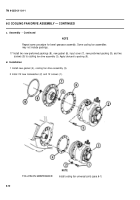
(c) Install dial indicator on bracket and position on gear teeth (50) as shown.
Back to Top


