TM-9-2350-311-34-1 - Page 254 of 352
TM 9-2350-311-34-1
9-2 BILGE PUMP — CONTINUED
a. Disassembly — Continued
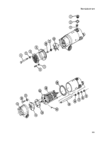
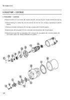
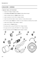
9 Remove Iockwire (27), four screws (28), retainer plate (29), and snap ring (30). Discard Iockwire and snap ring.
10 Remove bearing (31), retainer (32), and drive end bell (33) from rotor (34). Use tape or grease pencil to identify
bearing.
11 Remove commutator end bearing (35). Use tape or grease pencil to identify bearing.
12 Remove yoke (36) and gasket (37) from commutator end bell assembly (38). Discard gasket.
13 Remove four screws (39), four Iockwashers (40), connector (41), two gaskets (42), connector adapter (43),
and insulator sleeve (44). Discard Iockwashers and gaskets.
9-10
Back to Top


