TM-9-2350-311-34-1 - Page 258 of 352
TM 9-2350-311-34-1
9-2 BILGE PUMP — CONTINUED
c. Assembly — Continued
NOTE
Ensure bearings are installed at location as shown. Do not reverse installation of
bearings.
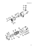
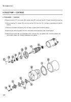
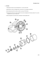
6 Install commutator end bearing (35) to rotor (34). Check label to correctly identify bearing.
7 Install drive end bell (33), retainer (32), and bearing (31) to rotor (34). Check label to correctly identify bearing.
8 Install new snap ring (30), retainer plate (29), four screws (28), and new Iockwire (27).
9 Install new gasket (25), four fiberglass sleeves (24), and drive end bell assembly (1 9). Replace studs (26) as
required.
10 Install four new gaskets (18), four flat washers (17), four new Iockwashers (16), and four nuts (15).
11 Install new gasket (23), seal cover (22), four new Iockwashers (21), and four screws (20).
12 Install drive end bell assembly (1 9), key (14), and impeller housing (13).
13 Install impeller (12) using fabricated removal/installation tool and install new Iockwasher (11) and nut (10).
14 Install impeller cover (9), inlet screen (8), four flat washers (7), and four screws (6).
15 Install four new Iockwashers (5) and four bolts (4).
16 Install four new brushes (3).
17 Install four new preformed packings (2) and four brush cap assemblies (1).
9-14
Back to Top


