TM-9-2350-311-34-1 - Page 257 of 352
TM 9-2350-311-34-1
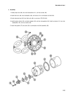
c. Assembly
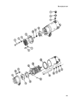
1 Install jumper wire (52), two new Iockwashers (51 ), and two screws (50).
2 Install field coils (46), new Iockwasher (46), and screw (47) to commutator end bell (50).
3 Solder electrical lead (45) from field coils (46) to connector (TB SIG 222).
4 Install insulator sleeve (44), connector adapter (43), and two new gaskets (42). Install connector (41), four new
Iockwashers (40), and four screws (39).
5 Install new gasket (37) and yoke (36) to commutator end bell assembly (36).
9-13
Back to Top

