TM-9-2350-311-34-1 - Page 263 of 352
TM 9-2350-311-34-1
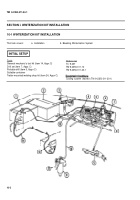
LEGEND
1 Rear battery winterization box
9
2 Front battery winterization box
10
3 Heater exhaust outlet
4 Coolant outlet hose
11
5 Coolant heater assembly
12
6 Electric fuel pump
13
7 Fuel filter
14
8 Heater coolant pump
15
a. Installation
Engine coolant right manifold
Primary fuel filter-to-coolant heater fuel filter
hose
Primary fuel filter
Main fuel supply hose
Winterization kit control box
Coolant heater harness
Coolant inlet hose
1 Remove batteries and mounting components (TM 9-2350-311-20-1). Retain all parts for kit installation except
battery tray screws.
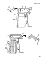
2 Move battery wiring harness (1) over hull slope plate (2) to allow clearance for installation of winterization kit
components.
3 Fold up front battery winterization box (3) and insert box through rear battery access opening (4). Locate box in
front battery access opening (5).
10-3
Back to Top

