TM-9-2350-311-34-1 - Page 268 of 352
TM 9-2350-311-34-1
10-1 WINTERIZATION KIT INSTALLATION — CONTINUED
a. Installation — Continued
18
19
20
21
22
23
24
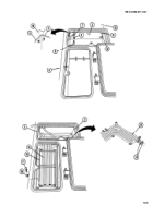
Place coolant heater assembly (33) on two coolant heater mounting brackets (20) and clamp with four
retaining bands (38) and four screws (39).
Install four retaining bands (38), two screws (40), two Iockwashers (41), and two nuts (42).
Install exhaust tube end support bracket (43), three flat washers (44), and three screws (45) to three hull front
plate tapping blocks. Close transmission access door to position exhaust tube end. Open door and tighten
screws. Install gasket (46).
Place clamp (47) on free end of 16-in. (40.6-cm) hose (28), install hose on coolant heater outlet elbow (32),
and tighten clamp.
Remove heater exhaust cover (48), three screws (49), and three flat washers (50) from inside left transmission
access door (51). Lift cover and gasket (52) from outside surface of door.
Install exhaust outlet (53) to left transmission access door (51) and install three screws (49), three flat washers
(50), and gasket (52).
Install exhaust outlet plug (54) in exhaust outlet (53).
10-8
Back to Top


