TM-9-2350-311-34-1 - Page 267 of 352
14
15
16
17
TM 9-2350-311-34-1
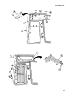
Place heater exhaust assembly (29) with hose clamp (30) in mounted position between coolant heater
mounting brackets (20).
Install inlet elbow (31) and outlet elbow (32) to coolant heater assembly (33).
Place hose clamp (34) over end of 0.625-in. - (1 5.9-mm-) id by 18-in. - (45.7-cm-) long hose (35). Install hose to
heater inlet elbow (31 ) and tighten clamp.
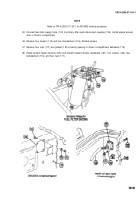
Place coolant heater assembly (33) in powerplant compartment as shown below. Connect heater exhaust
assembly (29) and install hose clamp (36) and screw (37).
10-7
Back to Top


