TM-9-2350-311-34-1 - Page 276 of 352
NOTE
TM 9-2350-311-34-1
10-1 WINTERIZATION KIT INSTALLATION — CONTINUED
a. Installation — Continued
49
50
51
52
53
54
55
56
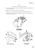
Connect coolant heater harness plug (123) to heater receptacle (1 24).
Connect harness lead (125) connector to heater coolant pump. Support harness lead with right headlight group
support strap.
Connect harness lead (circuit 402C) (126) to electric fuel pump connector.
Remove mounting screw (127) from coolant heater mounting bracket (20) and install harness ground lead
(128).
Remove two screws (129) and remove cover (130) from winterization kit heater control box (131 ).
Harness receptacle must face down. Reposition if necessary (para 10-2).
Remove two nuts (132) and two Iockwashers (133), place mounting bracket (134) on screws (135), and install
two nuts and two Iockwashers.
Install two screws (129) to cover (130).
Install mounting bracket (134), strap, control box (131), two flat washers (136), and two screws (137) to driver’s
compartment bulkhead tapping blocks (above engine compartment access door).
10-16
Back to Top


