TM-9-2350-311-34-1 - Page 278 of 352
TM 9-2350-311-34-1
10-1 WINTERIZATION KIT INSTALLATION — CONTINUED
a. Installation — Continued
59
60
61
62
63
64
NOTE
•
For vehicle circuitry incorporating the 3-position MASTER switch (one position
marked SLAVE), disconnect vehicle harness lead 459B at MASTER switch and
connect kit harness branch labeled 459B between MASTER switch and vehicle
harness lead 459B.
•
Steps 59 thru 61 apply to vehicles with engine model 7083-7396. Steps 62 thru 64
apply to vehicles with engine model 7083-7391.
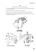
Disconnect existing lead 459B (143) at rear of portable instrument panel (144) MASTER switch (145) (TM 9-
2350-311-20-1).
Connect branch lead 459B (146) of control box-to-driver’s compartment wiring harness (147) to rear of
MASTER switch (145).
Connect existing lead (143) to other lead of control box-to-driver’s compartment lead 459B (146) or existing
lead of 459B (143).
Disconnect bulkhead-to-portable instrument-panel wiring harness lead 486A (148) from GLOW PLUG switch
(153) behind driver’s instrument panel.
Connect winterization heater control box-to-driver’s compartment harness lead 400 (150) to bulkhead-to-
portable instrument panel wiring harness lead 486A (148).
Connect winterization heater control box-to-drivers compartment harness lead 400 (150) to GLOW PLUG
switch (149).
10-18
Back to Top


