TM-9-2350-311-34-2 - Page 168 of 552
TM 9-2350-311-34-2
5-4 CANNON TUBE
This task covers:
a. Removal
b. Inspection
c. Installation
INITIAL SETUP
Tools
Artillery and turret mechanic’s tool kit
(SC 5180-95-CL-A12)
Artillery field maintenance tool kit
(SC 4933-95-CL-A06)
Fabricated breech stand (Figure C-3, Appx C)
Fabricated eyebolt assembly (Figure C-7, Appx C)
Sling, gun tube (item 19, Appx F)
Trolley, l-beam (item 25, Appx F)
Wrench, pipe, chain-type (item 27, Appx F)
OR
4" x 4" wooden block, min. 5’ long (item 37, Appx B)
Materials/Parts
Rag (item 26, Appx B)
Rope (item 27, Appx B)
Personnel Required
4
Equipment Condition
Park vehicle on level ground
Apply vehicle brake lock handle
Vehicle MASTER switch to OFF (TM 9-2350-311-10)
Travel lock removed and stowed (TM 9-2350-311-10)
Cannon assembly positioned at 0° traverse and 0° ele-
vation (TM 9-2350-311-10)
Drain equilibration system manifold
(TM 9-2350-311-20-2)
Turret lock in LOCKED position (TM 9-2350-311-10)
Muzzle brake removed (TM 9-2350-311-10)
Bore evacuator removed (TM 9-2350-311-10)
Dust shield removed (TM 9-2350-311-20-2)
Torque key removed (TM 9-2350-311-20-2)
a. Removal
Wear gloves and steel-tipped safety shoes to avoid possible injury.
When working on mount and cannon assembly breech components with cannon assembly
pushed out of battery, block cannon assembly by placing fabricated breech stand under breech
body to prevent accidental elevation of cannon assembly and possible injury to personnel or
damage to equipment.
NOTE
Cannon assembly may have to be pushed out of battery (TM 9-2350-311-20-2) to gain access to
cap screw.
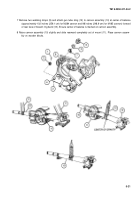
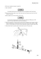
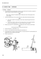
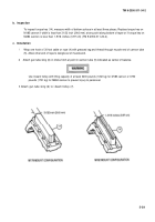
1
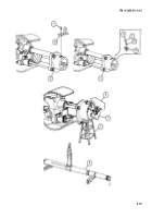
Loosen cap screw (1).
2 Slide breech ring machine key (2) up and out of slot (3). Do not remove cap screw or breech ring machine key.
3 Tighten cap screw (1).
5-24
Back to Top


