TM-9-2350-311-34-2 - Page 164 of 552
TM 9-2350-311-34-2
5-3 CANNON ASSEMBLY (MOUNT OFF CAB)
This task covers:
a. Disassembly
b. Assembly
INITIAL SETUP
Tools
Artillery and turret mechanic’s tool kit
(SC 5180-95-CL-A12)
Artillery field maintenance tool kit
(SC 4933-95-CL-A06)
Sling, gun tube (item 19, Appx F)
Trolley, l-beam (item 25, Appx F)
Materials/Parts
Cotter pin (item 48, Appx E)
Key washers (2) (item 114, Appx E)
M109A2/M109A3/M109A4
Key washers (2) (item 143, Appx E) M109A5
Webbing straps (2) (item 34, Appx B)
Wooden blocks (item 37, Appx B)
Personnel Reauired
3
Equipment Condition
Muzzle brake removed (TM 9-2350-311-10)
Thrust collar removed (TM 9-2350-311-10)
Bore evacuator removed (TM 9-2350-311-10)
Dust shield removed (TM 9-2350-311-20-2)
Torque key removed (TM 9-2350-311-20-2)
Nitrogen pressure released from recuperator assembly
(para 5-11)
a. Disassembly
1
2
3
4
5
6
Wear gloves and steel-tipped safety shoes to avoid possible injury while handling heavy equipment.
NOTE
Trunnion bracket does not have to be removed for cannon assembly removal.
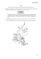
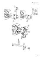
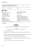
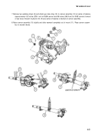
Remove and discard cotter pin (1).
While holding shaft collar (2) with pipe wrench, remove slotted nut (3) from recuperator piston shouldered
shaft (4).
Unlock two key washers (5). Remove two round nuts (6), two key washers (5), and two keyway washers (7)
from two variable recoil cylinder rods (8) using spanner wrench. Discard key washers.
Attach two webbing straps (9) to cannon assembly (10) and to l-beam trolley (not shown).
Raise l-beam trolley (not shown) to remove slack from two webbing straps (9) and slide cannon assembly
(10) rearward 3 feet (91.4 cm).
Lower cannon assembly (10) and mount (11) as an assembly onto wooden blocks.
5-20
Back to Top

