TM-9-2350-311-34-2 - Page 162 of 552
5-18
TM 9-2350-311-34-2
5-2 CANNON ASSEMBLY (CAB ON VEHICLE) - CONTINUED
b. Installation - Continued
8
9
10
11
12
13
14
15
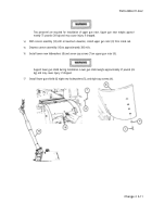
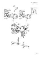
While holding shaft collar (5) with pipe wrench, install slotted nut (6) on recuperator piston shouldered shaft
(7). Slotted nut should be tightened until slotted nut and shaft collar are just beginning to touch breech ring
body (3).
Loosen slotted nut (6) 1/6 to 1/3 turn while alining cotter pin (4) hole in recuperator piston shouldered shaft
(7) with slots in slotted nut. Install new cotter pin.
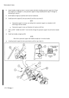
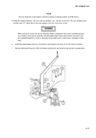
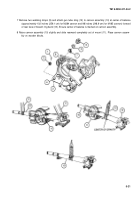
Remove fabricated eyebolt lifting bracket (18) and three cap screws (11) from top of breech ring body (3).
NOTE
Lockwire is used to secure interlocking stop on M284 cannon. Three Iockwashers are used on M185
cannon.
Install interlocking stop (10) using three cap screws (11) from fabricated eyebolt lifting bracket (18) with new
Iockwire (12) or three new Iockwashers (13).
Assemble breech mechanism (8) (para 5-5), if disassembled.
Install cannon tube (9) (para 5-4).
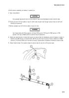
Fill equilibration system with hydraulic fluid (TM 9-2350-311-20-2).
Remove fabricated breech stand (2) from under breech ring body (3).
NOTE
After cannon assembly replacement, all fire control components must be checked for alinement
(TM 9-2350-311-20-2).
Adjustment of operating cam roller clearance is required after cannon assembly replacement
(TM 9-2350-311-20-2).
Back to Top


