TM-9-2350-311-34-2 - Page 170 of 552
TM 9-2350-311-34-2
5-4 CANNON TUBE - CONTINUED
a. Removal - Continued
10
11
12
13
14
15
16
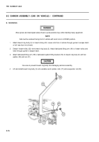
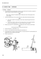
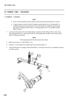
Place fabricated breech stand (8) between the breech ring (9) and the floor of the vehicle, as required, to
support the breech ring after withdrawal of cannon assembly.
NOTE
Refer to steps 13 through 15 for alternate method of rotating cannon tube if chain-type pipe wrench
is NOT available.
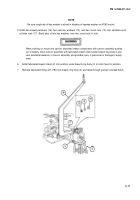
install chain-type pipe wrench (10) on cannon tube (5) at a location without critical external features.
NOTE
Cannon tube is rotated 45° when keyway on cannon tube is alined with upper left bolt hole for
dust shield.
If cannon tube is difficult to rotate, some of the nitrogen pressure in the recuperator assembly
may have to be discharged (para 5-11) to relieve binding on breech ring band.
Rotate cannon tube (5) 45° counterclockwise to disengage cannon tube from breech ring (9) threads.
NOTE
If chain-type pipe wrench has been used, skip to step 17.
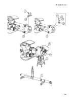
Install muzzle brake (11) (TM 9-2350-311-10).
Insert a 4 x 4 inch wooden block at least 5 feet long into muzzle brake (11).
Using wooden block for leverage, rotate muzzle brake (11) and cannon tube (5) 45° counterclockwise to dis-
engage cannon tube from breech ring (9) threads.
Remove muzzle brake (11).
5-26
Back to Top

