TM-9-2350-311-34-2 - Page 178 of 552
TM 9-2350-311-34-2
5-4 CANNON TUBE - CONTINUED
c. Installation - Continued
18
19
20
21
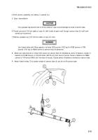
To install breech ring machine key (2), loosen cap screw (1). Slide breech ring machine key downward into
slot (3) and tighten cap screw.
Charge recuperator assembly (TM 9-2350-311-20-2).
Remove l-beam trolley (7), gun tube sling (6), and chain-type pipe wrench (10) or 4 x 4 inch wooden block
from cannon tube (5). Remove fabricated breech stand (8) from under breech ring (9).
Cannon assembly will not be fired until cannon tube and breech ring are properly assembled, alined
and adjusted.
inspect position of breech ring machine key (2). Breech ring machine key should fill all but the rounded end
.
.
of the slot. This is difficult to see with cannon assembly installed in mount; feel with little finger to make sure.
After anew M284 cannon assembly or its machine key has been installed, a zone 6 charge must be
fired to mate machine key and the cannon tube. Failure to follow this procedure could result in equip-
ment damage.
NOTE
After cannon assembly replacement, all fire control components must be checked for alinement
(TM 9-2350-311-20-2).
Adjustment of operating cam roller clearance is required after cannon assembly replacement
(TM 9-2350-311-20-2).
5-34
Back to Top


