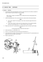
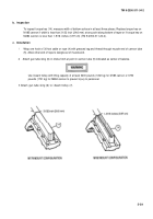
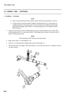
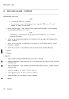
TM-9-2350-311-34-2 - Page 180 of 552
TM 9-2350-311-34-2
5-5
BREECH MECHANISM - CONTINUED
a. Disassembly - Continued
NOTE
Do not remove breech ring from cannon.
Lockwire is used to secure interlocking stop to breech ring body of M284 cannon. Three lock-
washers are used on the M185 cannon.
1
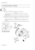
Remove three cap screws (1) three lockwashers (2) or lockwire (3) and interlocking stop (4) from breech
ring body (5). Discard lockwashers or lockwire.
NOTE
Lockwire is used to secure left (lower) and right (upper) catches of M284 cannon. Four lockwashers
are used on M185 cannon.
2
Remove two cap screws (6) two lockwashers (7) or lockwire (8) and right (upper) catch (9). Discard lock-
washers or lockwire.
3
Remove two cap screws (10), two lockwashers (11) or lockwire (12), and left (lower) catch (13). Discard
lockwashers or lockwire.
4
Remove two cap screws (14) two lockwashers (15) and control cam (16). Discard lockwashers.
5 Deleted.
6 Deleted.
b. Inspection
1
Inspect breech ring body (5) (TM 9-1000-202-14) and replace as required.
2
Measure inside diameter of upper breech ring lug (17) and replace breech ring body (5) if greater than 2.910
inches (7.39 cm).
3
Measure inside diameter of lower breech ring lug (18) and replace breech ring body (5) if greater than 3.004
inches (7.63 cm).
4
Inspect interlocking stop (4). Replace if cracked or deformed.
5
Inspect right (upper) catch (9). Replace if cracked or deformed.
6
Inspect left (lower) catch (13). Replace if cracked or deformed.
7 Deleted.
5-36
Change 2
Back to Top

