TM-9-2350-311-34-2 - Page 184 of 552
TM 9-2350-311-34-2
5-6
BREECHBLOCK ASSEMBLY - CONTINUED
b. Inspection and Repair
1
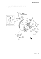
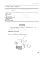
Inspect breechblock (1) for damaged threads. Repair threads or replace breechblock.
2
Measure breechblock (1) hole diameter (5). Replace if greater than 4.318 inches (10.968 cm).
3
Inspect gear segment (6) of breechblock (1). Replace breechblock if damaged or distorted.
4
Replace roller (4) if broken, cracked, if outside diameter is less than 0.995 inch (25.273 mm), or if inside di-
ameter is greater than 0.506 inch (12.852 mm).
5
Inspect headed straight pin (3). Replace if damaged or distorted.
6 Deleted.
c. Assembly
NOTE
If headed straight pin is new from supply, preform step 2.
1
Install roller (4) and headed straight pin (3) in breechblock (1).
2
Drill a 5/32 hole in the headed straight pin using the hole in the breechblock as a pilot hole. Ensure roller (4)
is free to turn and not bound.
3
Install new spring pin (2).
5-40
Change 2
Back to Top

