TM-9-2350-311-34-2 - Page 192 of 552
TM 9-2350-311-34-2
5-48
5-10 BREECH CAM AND PIN ASSEMBLY
This task covers:
a. Removal/Disassembly
b. Inspection
c. Assembly/lnstallation
INITIAL SETUP
Tools
Artillery and turret mechanic’s tool kit
(SC 5180-95-CL-A12)
Artillery field maintenance tool kit
(SC 4933-95-CL-A06)
Fabricated hinge pin bushing driver (Figure C-9,
Appx C)
Materials/Parts
Bushings (2) (item 118, Appx E)
Self-locking nut (item 42, Appx E)
Self-locking nut (item 43, Appx E)
Spring pin (item 106, Appx E)
Personnel Reauired
2
Equipment Condition
M118A2/M118A3 elbow telescope removed
(TM 9-2350-311-10)
Cannon tube in travel lock (TM 9-2350-311-10)
Damper assembly removed (TM 9-2350-311-20-2)
a. Removal/Disassembly
Wear safety shoes, gloves, and safety glasses to prevent injury.
1
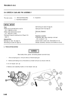
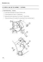
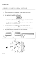
Drive out spring pin (1) from pin collar (2). Discard spring pin.
2
Remove self-locking nut (3), flat washer (4), breech cam pin (5), and pin collar (2).
3 Lift off breech cam (6).
4 Remove cam assembly handle (7) from breech cam (6).
Back to Top

