TM-9-2350-311-34-2 - Page 196 of 552
TM 9-2350-311-34-2
5-10
BREECH CAM AND PIN ASSEMBLY - CONTINUED
c. Assembly/Installation - Continued
2
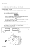
Bore new bushings (9 and 10) to an inside diameter of 0.740 ± 0.005 inch (18.8 ± 0.13 mm).
3
Install new bushing (9) with hinge pin bushing driver (12).
4
Install new bushing (10) with hinge pin bushing driver (12).
Be careful not to damage threads in lubrication holes when drilling holes in new bushings. Remove
all burrs from drilled holes in bushings. This will prevent improper fit.
NOTE
Use a 90° angle electrical drill. If not available, push cannon assembly out of battery
(TM 9-2350-311-20-2) and use regular style drill.
5
Drill 1/8 inch (3.2 mm) hole in new bushings (9 and 10) through lubrication fitting (8) holes.
NOTE
New bushings must be reamed in one operation as shown so they will be in line with each other.
6
Ream bushings (9 and 10) with a hand reamer, 3/4 inch (19.05 mm) in diameter.
7
Install two lubrication fittings (8) on hinge (11).
5-52 Change 2
Back to Top


