TM-9-2350-311-34-2 - Page 190 of 552
TM 9-2350-311-34-2
5-9 HANDLE ASSEMBLY
This task covers:
a. Disassembly
c. Assembly
b. Inspection
INITIAL SETUP
Tools
Materials/Parts
Artillery and turret mechanic ’s tool kit
Spring pin (item 3, Appx E)
(SC 5180-95-CL-A12)
Spring pin (item 94, Appx E)
Artillery field maintenance tool kit
Equipment Condition
(SC 4933-95-CL-A06)
Handle assembly removed (TM 9-2350-311-20-2)
a. Disassembly
1
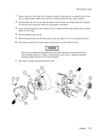
Place handle assembly (1) on a solid work surface. Actuate detent plunger (2) to see if it returns to locked
position.
2
Remove spring pin (3), detent plunger (2), and helical compression spring (4) from operating handle (5).
Discard spring pin.
3
Actuate clutch disk (6) to see if it returns to position when released.
4
Remove spring pin (7), helical compression spring (8), and clutch disk (6) from operating handle (5). Discard
spring pin.
b. Inspection
1
Inspect helical compression spring (4). Replace if distorted or it failed to return detent plunger (2) to locked
position when actuated during disassembly procedure.
2
Measure inside diameter of operating handle (5). Replace if greater than 3.743 inches (9.507 cm).
3
Inspect helical compression spring (8). Replace if distorted or it failed to return clutch disk (6) to proper posi-
tion during disassembly procedure.
4
Inspect clutch disk (6). Replace if nicked, distorted, or cracked.
c. Assembly
1
Install helical compression spring (8) and clutch disk (6). Secure by installing new spring pin (7).
2
Install helical compression spring (4) and detent plunger (2). Secure detent plunger by pushing into operat-
ing handle (5) and installing new spring pin (3).
5-46
Back to Top

