TM-9-2350-311-34-2 - Page 352 of 552
TM 9-2350-311-2
6-18 CONTROL ASSEMBLY - CONTINUED
a. Disassembly - Continued
Restrain gunner’s control cover while removing cap screws to avoid injury. Gunner’s control cover
holds two helical compression springs.
17
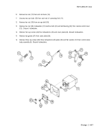
Remove four cap screws (32), four lockwashers (33), and gunner’s control cover (34). Discard lockwashers.
18
Remove two helical compression springs (35) and support (36).
Retaining rings and retainers hold small helical compression springs. Restrain retainer as retaining
ring is removed to avoid injury.
19
Remove two retaining rings (37), two flat washers (38) two helical compression springs (39) and two helical
compression seats (40). Discard retaining rings.
20
Remove two retaining rings (41) and discard.
21
Withdraw traversing sleeve and slide assembly (42) out of front end of body (43).
22
Remove elevating sleeve and slide assembly (44) plug (45) and preformed packing (46). Discard
preformed packing.
23
Remove two preformed packings (47) from elevating sleeve and slide assembly (44) and discard.
24
Remove seven preformed packings (48) from elevating sleeve and slide assembly (44) and discard.
25
Remove two preformed packings (49) from traversing sleeve and slide assembly (42) and discard.
26
Remove seven preformed packings (50) from traversing sleeve and slide assembly (42) and discard.
b. Inspection
1
Inspect connecting link (11). Replace if bent, distorted, or damaged.
2
Inspect remote control lever (13). Replace if bent, distorted, or damaged.
3
Inspect end rod clevis (14). Replace if bent or threads are damaged.
4
Inspect cover plate (26). Replace if it does not fit flat on plate (30).
5
Inspect plate (30). Replace if cracked or warped.
6
Inspect gunner’s control cover (34) and body (43). Replace if cracked, distorted, or damaged.
7
Inspect two helical compression springs (35) and two helical compression springs (39). Replace if cracked.
fatigued, or scratched.
6-88 Change 2
Back to Top


