TM-9-2350-311-34-2 - Page 356 of 552
TM 9-2350-311-34-2
6-18 CONTROL ASSEMBLY - CONTINUED
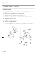
c. Assembly - Continued
13
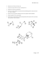
Install ball bearing (23), machine bolt (22), new lockwasher (21), and hex nut (20) on remote control lever
(13).
14
Install hex nut (19) on one eyebolt (18).
15
Screw one eye bolt (18) into each end of connecting link (11).
16
Install hex nut (17) on end rod clevis (14).
17
Install new retaining ring (15) and headed grooved pin (16) on end rod clevis (14).
18
Screw end rod clevis (14) into control valve body assembly (6).
19
Install remote control lever (13) and new retaining ring (12).
20
Install connecting link (11) headed grooved pin (10), and new retaining ring (9).
6-92 Change 2
Back to Top


