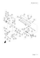
TM-9-2350-311-34-2 - Page 362 of 552
TM 9-2350-311-34-2
7-1 RAMMER ASSEMBLY
This task covers:
a. Removal
b. Disassembly
c. Inspection and Repair
d. Assembly
e. Installation
f. Adjustment
INITIAL SETUP
Tools
Artillery and turret mechanic’s tool kit
(SC 5180-95-CL-A12)
Artillery field maintenance tool kit
(SC 4933-95-CL-A06)
Materials/Parts
Antiseizing compound (item 5, Appx B)
Cotter pins (2) (item 45, Appx E)
Grease (item 21, Appx B)
Gasket cover (item 127, Appx E)
LockWashers (8) (item 71, Appx E)
LockWashers (7) (item 75, Appx E)
LockWashers (6) (item 84, Appx E)
LockWire (item 39, Appx E)
Lockwire (item 107, Appx E)
Retaining rings (2) (item 125, Appx E)
Sealing compound (item 29, Appx B)
Spring pin (item 4, Appx E)
Personnel Required
2
Equipment Condition
Cannon set at 0° elevation (TM 9-2350-311-10)
Discharge and drain hydraulic system
(TM 9-2350-311-20-2)
Rammer lines and fittings removed
(TM 9-2350-311-20-2)
Tension on adjuster relieved (TM 9-2350-311-10)
a. Removal
1
Remove four hex nuts (1), four cap screws (2), four Iockwashers (3), and blocking check valve (4). Discard
lockwashers.
Be careful when opening breechblock with spring tension released. Use operating handle to sup-
port breechblock as it is being opened. Otherwise, carrier will slam open and maybe damaged.
2
Open breechblock (5).
3
Move rammer assembly (6) to ram position.
4
Remove lockwire (7), two cap screws (8), and rammer mounting bracket (9). Discard lockwire.
5
Remove lockwire (11), two cap screws (11), two Iockwashers (12), and angle bracket (13). Discard lock-
washers and lockwire.
7-2
Back to Top


