TM-9-2350-311-34-2 - Page 366 of 552
TM 9-2350-311-34-2
7-1 RAMMER ASSEMBLY - CONTINUED
b. Disassembly
1
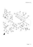
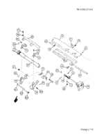
Remove elbow (26.1) metallic tube (26.2) adapter (26.3) and adapter (26.4).
2
Remove four cap screws (27) four fiat washers (28) and rammer handle (29).
3
Remove four cap screws (30) and two caps (31). Identify each cap with its cylinder support (32). Two caps
and front and rear cylinder supports are matched sets.
4
Remove and discard upper half of retaining ring (33).
5
Remove cylinder assembly (34).
6
Remove and discard lower half of retaining ring (33).
7
Remove cotter pin (35) and flat washer (36) from headed straight pin (37). Discard cotter pin.
8
Withdraw headed straight pin (37) from rod end bearing (38).
9
Remove two cap screws (39) and two flat washers (40) from angle bracket (41).
10
Remove four cap screws (42) and handle group (43) from loader-rammer tray (44).
11
Remove seven cap screws (45), two cap screws (46) latch (47) and loader-rammer tray (44).
12
Remove two cap screws (48) and mounting bracket (49) from loader-rammer tray (44).
NOTE
A 0.25 inch (6.4 mm) threaded hole in end of electrical post can be used to install a pulling device to
remove electrical post.
13
Remove electrical post (50).
NOTE
Front and rear cylinder supports and two caps are matched sets. Keep parts together when disas-
sembled.
14
Remove two front and rear cylinder supports (32) and retain together with two caps (31).
15
Remove hex nut (51) shoulder bolt (52), flat washer (53), lock-release lever (54) and helical torsion spring
(55) from front cylinder support (32).
16
Remove machine key (56) from rear cylinder support (32).
7-6 Change 2
Back to Top


