TM-9-2350-311-34-2 - Page 374 of 552
TM 9--2350--311--34--2
7--14
Change 2
7--1
RAMMER ASSEMBLY — CONTINUED
d. Assembly — Continued
12
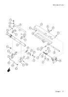
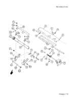
Install machine key (56) in rear cylinder support (32).
13
Apply sealing compound to threads of hex nut (51) and shoulder bolt (52). Install helical torsion spring (55),
lock-release lever (54), flat washer (53), shoulder bolt (52), and hex nut (51) to front cylinder support (32).
Torque shoulder bolt to 34--42 lb-ft (46--57 N
.
m).
NOTE
Front and rear cylinder supports and caps are matched sets.
14
Install front and rear cylinder supports (32) and caps (31).
15
Install electrical post (50).
16
Install mounting bracket (49) and two cap screws (48) to loader-rammer tray (44).
17
Apply sealing compound to threads of seven cap screws (45). Install loader-rammer tray (44), latch (47), two
cap screws (46), and seven cap screws. Torque five cap screws to 32--39 lb-ft (43--53 N
.
m).
18
Install handle group (43) and four cap screws (42) on loader-rammer tray (44).
19
Install two flat washers (40) and two cap screws (39) on angle bracket (41).
20
Insert headed straight pin (37) into rod end bearing (38).
21
Install flat washer (36) and new cotter pin (35) on headed straight pin (37).
22
Install new lower half of retaining ring (33).
23
Install cylinder assembly (34).
24
Install new upper half of retaining ring (33).
NOTE
Be sure to install two caps with their respective matched front and rear cylinder supports.
25
Install two caps (31) and four cap screws (30).
26
Install rammer handle (29), four flat washers (28), and four cap screws (27).
27
Install adapter (26.4), adapter (26.3), metallic tube (26.2), and elbow (26.1).
Back to Top


