TM-9-2350-311-34-2 - Page 378 of 552
TM 6-2350-311-34-2
7-1 RAMMER ASSEMBLY - CONTINUED
e. Installation - Continued
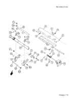
9
Install angle bracket (13) two new lockwashers (12), and two cap screws (11). Do not tighten two cap
screws yet.
NOTE
Do not spot paint bridge cover clamp or plunger. Lubricate with grease.
10
Adjust angle bracket (13) so that plunger (88) of blocking check valve (4) is depressed when rammer as-
sembly (6) is in ram position, then tighten two cap screws (11). Secure two cap screws with new lockwire
(10).
11
Install rammer mounting bracket (9), two cap screws (8), and new lockwire (7).
12
Move rammer assembly (6) to retracted position.
13
Reset tension on adjuster (TM 9-2350-311-10).
14 Close breechblock (5).
15
Install blocking check valve (4), four new lockwashers (3), four cap screws (2) and four hex nuts (1).
7-18 Change 2
Back to Top


