TM-9-2350-311-34-2 - Page 372 of 552
TM 9--2350--311--34--2
7--12
Change 3
7--1
RAMMER ASSEMBLY — CONTINUED
d. Assembly
1
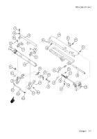
Install straight shaft (87) on rammer support (60).
2
Install flat washer (86), nonmetallic bushing (85), and shoulder screw (84).
3
Install shaft cover assembly (83), four spring tension washers (82), and four cap screws (81) on rear of
rammer support (60). Secure four cap screws with new lockwire (80).
4
Install two lubrication fittings (79).
5
Install cap screw (78).
6
Install new cover gasket (77), access cover (76), seven new lockwashers (75), and seven machine
screws (74) on rammer support (60).
7
Install rammer switch actuator (73), flat washer (72), helical compression spring (71), dial pointer (70), and
headless shoulder pin (69).
8
Install actuating lock lever (68), headed straight pin (67), flat washer (66), and new cotter pin (65).
9
Install new spring pin (64).
10
Install cover assembly (63), five flat washers (62), and five machine screws (61) to rammer support (60).
11
Apply sealing compound to threads of four cap screws (58) and two cap screws (57). Install tray support
(59), four cap screws (58), and two cap screws (57) to flange of rammer support (60). Torque cap screws to
32--39 lb-ft (43--53 N
.
m).
Back to Top


